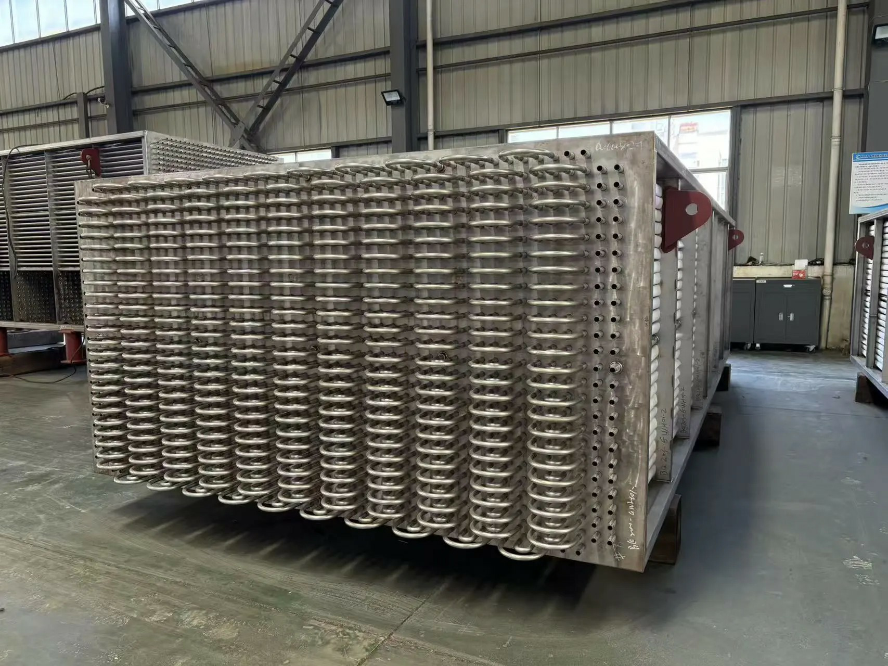

Time: Jul 6 2026 Views: 88
INTRODUCTION
Pressure drop optimization is the engineering process of minimizing flow resistance in heat exchanger systems while maintaining efficient heat transfer performance.
In industrial flue gas heat recovery systems, pressure drop directly impacts:
● fan energy consumption
● net system efficiency
● operational cost
● system stability
● equipment sizing
Optimizing pressure drop is essential for achieving high-performance and economically viable heat recovery systems.
WHAT IS PRESSURE DROP?
Flow Resistance in Heat Exchanger Systems
Pressure drop refers to the reduction in gas pressure as flue gas passes through a heat exchanger system due to:
● friction along tube surfaces
● changes in flow direction
● obstruction from heat exchange structures
● turbulence generation
Higher pressure drop means higher energy required to move gas through the system.
WHY PRESSURE DROP MATTERS
Energy Efficiency Is Affected by Flow Resistance
In heat recovery systems:
* recovered heat increases system efficiency
* but high pressure drop increases fan power consumption
This creates a system-level trade-off:
> Energy gained from heat recovery vs energy consumed by airflow resistance
Net efficiency depends on balancing both factors.
KEY FACTOR 1 — FLOW CHANNEL DESIGN
Geometry Determines Resistance
Flow path design strongly influences pressure drop.
Poor design can cause:
● flow stagnation zones
● excessive turbulence
● uneven gas distribution
Optimized design ensures:
● smooth flow paths
● uniform velocity distribution
● reduced turbulence losses
KEY FACTOR 2 — HEAT TRANSFER SURFACE DENSITY
Surface Area vs Flow Resistance Trade-Off
Although this equation describes electrical resistance, the analogy applies in fluid systems:
> More parallel flow paths reduce resistance, while dense structures increase resistance.
In heat exchangers:
● higher surface density improves heat transfer
● but increases pressure drop
Engineering design must balance both.
KEY FACTOR 3 — GAS VELOCITY CONTROL
Higher flue gas velocity leads to:
● improved heat transfer
● increased pressure loss
Lower velocity leads to:
● reduced pressure drop
● lower heat transfer efficiency
Optimal design targets a controlled velocity range based on system conditions.
KEY FACTOR 4 — FOULING AND BLOCKAGE
Deposits on heat transfer surfaces significantly increase pressure drop over time.
Causes include:
● dust accumulation
● chemical scaling
● condensation residue
Effects:
● reduced flow area
● increased resistance
● higher maintenance frequency
Anti-fouling surface design is critical for long-term stability.
KEY FACTOR 5 — MATERIAL AND SURFACE ROUGHNESS
Surface characteristics affect friction losses:
● rough surfaces → higher resistance
● smooth surfaces → lower resistance
Fluoroplastic surfaces offer:
● lower surface energy
● reduced adhesion
● smoother flow behavior
This helps reduce long-term pressure increase caused by fouling.
KEY FACTOR 6 — SYSTEM LAYOUT DESIGN
Global System Resistance Matters More Than Local Optimization
Pressure drop is not determined by a single component.
It depends on:
● duct layout
● exchanger arrangement
● bends and transitions
● system integration
Poor layout design can significantly increase total system resistance.
ENGINEERING SOLUTION STRATEGY
How Pressure Drop Is Optimized
Effective strategies include:
1. Flow Path Optimization
● streamline gas flow
● reduce sharp turns
● eliminate dead zones
2. Balanced Heat Transfer Design
● optimize surface area vs resistance
● avoid over-densification of tubes
3. Anti-Fouling Surface Engineering
● reduce dust adhesion
● minimize long-term blockage
4. Composite Structural Design
Fluoroplastic-steel systems help maintain:
● smooth flow surfaces
● stable long-term resistance
● reduced fouling buildup
KEY INSIGHT
Pressure Drop Determines Net System Efficiency
Even highly efficient heat recovery systems can perform poorly if:
● pressure drop is too high
● fan energy consumption exceeds thermal gain
> True system efficiency is the balance between heat recovery and flow energy cost.
CONCLUSION
Pressure drop optimization is a fundamental requirement in industrial heat recovery system design.
By carefully balancing:
● flow dynamics
● heat transfer efficiency
● fouling resistance
● system layout
engineers can achieve:
● higher net energy recovery
● lower operating cost
● improved system stability
● longer equipment lifespan

@ 2025-2026 Langteng Machinery. All Rights Reserved.